Notes on setting up various aspect of the system.
Table of Contents.
1. Networking Setup for the Dome controllers
2. Mint WorkBench Installation Notes
3. E100 IO Summary
Appendix A - Summary of Vel, Accel Limits
Appendix B - Running AutoTune from WorkBench
1. Networking Setup for the Dome controllers
Setup the Baldor Ethernet Powerlink Rounter. This router allows you to
attach the EPL network (e100 ethernet) to your facility's subnet.
See MN1958 manual for instructions.
The router is configure via web brower.
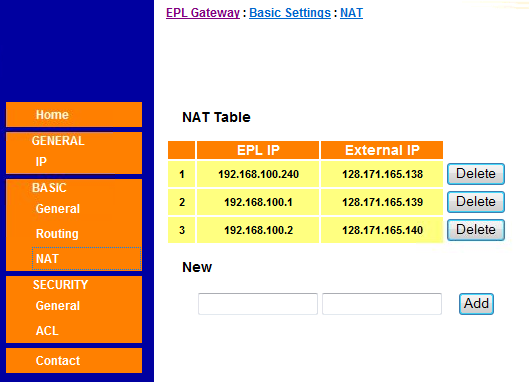
hostname EPL Network IP SUMMIT IP Number Hilo IP Number NodeID
----------- --------------- --------------- -------------- ---------
t3epl 192.168.100.254 128.171.165.137 128.171.110.226 0xFE (default)
t3e100-0 192.168.100.240 128.171.165.138 128.171.110.227 0xF0 (240, manager node)
t3e100-1 192.168.100.001 128.171.165.139 128.171.110.228 0x01 (axis 1, control node)
t3e100-2 192.168.100.002 128.171.165.140 128.171.110.229 0x02 (axis 2, control node)
Browser Screen shot: BASIC NAT screen
 2. Mint WorkBench Installation Notes
We are using PC running Windows 7 Professional 64-bit as our host PC for MINT WorkBench.
The window Installation is very basic:
Install windows professional 7 64-bit.
Name it mintpc
Apply all updates
Install misc applications: McAfee anti-virus, VNC, ssh, syncback.
Installed Mint WorkBench Build 5704 on Win7 computer
Archived software and manuals here: http://irtfweb.ifa.hawaii.edu/~tcs3/tcs3/vendor_info/Baldor/
Had error about "Mint option card firware version mismatch", so I download new
firmware on all 3 controllers. See 1208-firmware_update.html.
Firmware update on all 3 controller were done on 12-08-09.
When installing on a new pc :
1. Install "Mint WorkBench Build 5704 Setup.exe"
2. Import "MotiFlex e100 Build 5633.msx" into workbench.
Start workbench, then use "Tool->Install Mint System Files..", select the .msx file.
To check out the motor, we ran each on in standalone mode. Goal was to configure and
run the autotune (unloaded shaft) for each motor. The all pasted diagontics on
12/09/28: 120907-config-standalone.html.
3. E100 IO Summary
The E100 Standard IO on X3 connector:
Has 1 Analog in (AIN0).
DriveEnable Input
3 Digitial Inputs (DIN0, DIN1, DIN2)
2 Digitial Outputs (DOUT0, DOUT1 )
+-----------------------------------------------------------------------------------------------+
| e100 IO | MasterNode | Slave Node1 | Slave Node2 | TCS3 |
+-----------------------------------------------------------------------------------------------+
| AIN0 | | 24V UPS | 24V UPS | FIOE AO |
| | +/- 10V Vel | monitor | monitor | mod15.ch2 |
+-----------------------------------------------------------------------------------------------+
| DriveEnable Input | TCS Safety Circuit "DOME_AMP_ENABLE" signal | safety board |
+-----------------------------------------------------------------------------------------------+
| DIN0 | 24V_DIG - 3 phase power monitor | n/a |
+-----------------------------------------------------------------------------------------------+
| DIN1 | TCS OPTO22 | N/C | N/C | FIOE DO |
| | "vel_enable" | | | Mod14.Ch3 |
+-----------------------------------------------------------------------------------------------+
| DIN2 | reset_e100 | reset_e100 l reset_e100 | FIOE DO |
| | | | | Mod14.Ch4 |
+-----------------------------------------------------------------------------------------------+
| DOUT0 | e100_error | e100_error | e100_error | FIOE DI |
| | | | | Mod13.Ch2 |
+-----------------------------------------------------------------------------------------------+
| DOUT1 | Motor Brake Rel | Motor_Brake_Rel | Motor_Brake_Rel | n/a |
+-----------------------------------------------------------------------------------------------+
DIN2 used to reset controller from TCS. (RESETINPUT = 2)
DOUT0 used to indicate global error to TCS (GLOBALERROROUTPUT=0)
The manager Node has the MINT option card installed. We are not
using any of the IO on the MINT module. The mint module has:
1 Analog Input: AIN8
1 Analog Output: AOUT8
4 Digital Input: DIN32, 33, 34, 35.
4 Digital Output: DOUT32, 33, 34, 35.
Appendix A - Summary of Vel, Accel Limits
Max Dome Vel is 2.0 deg/sec.
Max Dome accel is 0.166 deg/sec.
Gearing Ratio between Motor shaft and Dome:
Ratio New_Wheel Old_Wheel
--------- ---------- ----------
gearbox 24.64 24.64
spurgear 3.62 3.62 // spurgear 76/21
bogie wheel 38.4 38.88
Total Ratio: 3424.256 3467.6010
Ratio old vs new: 0.9875 1.012658
The gearbox ratio is: 24.64
The spurgear ratio is: 76/21=3.62
The bogie wheel to dome ratio is: 768/20=38.4
The total ratio is: 3424.2559
The New wheel was based on the drawing (768/20) ratio.
The Old wheel is the measured bogie Wheel (768/19.75 ) ratio.
We need 3424.2559 rotations of the motor shaft to have a 1 revolution of the dome.
1 Motor Rotation has 4096 encoder counts.
Baldor suggest we set the scale factor to 4096 so counts and motor rotations are equal.
User Unit are in R/S.
rpm2deg = 0.0017522054937541322 // Motor RPM to Dome deg/sec
// R/M * 1/60 min/sec * 360 deg/rot / 3424.2559 gearing
uu2deg = 0.10513232962524792 // Motor UU to Dome deg/sec
// R/S * 360 deg/rot / 3424.2559 gearing
deg2rpm = 570.70931666666672 // Dome deg/sec to Motor RPM
// deg/s * (1 rot/360 deg) * (60sec/min) * 3424.2559
deg2uu = 9.5118219444444456 // Motor UU r/s to Motor RPM
// r/s * (1 r/360 deg) * 3424.2559
|---------------------------------------|
| Dome deg/sec | Motor RPM | UU R/S |
|---------------------------------------|
Max Vel:| 2.0 | 1141.41 | 19.0236 |
|----------------------------|----------|
Max Acc:| 0.166 | 94.7377 | 1.57896 |
|---------------------------------------|
Dome Rail Re-surfacing speed.
We need 3424.3 retations of the motor staff to have a complete revolution of the dome.
The perimeter of the dome is 768*PI = 2412.7 inches.
So for each revolution of the motor shaft, the dome will travel 2412.7/3424.3 = 0.70459456 inches
If the cutting travel speed is X in/min then the motor speed will be (X / 0.70459456) rpm
For X = 10in/min
10/0.70459456 = 14.1925 RPM. or 14.1925/60.0 = 0.23654265 R/S.
(that would be 0.1234416 volts on the AD VelRef input)
For X = 15in/min
15/0.70459456 = 21.2888 RPM. or 21.2888/60.0 = 0.35481397 R/S.
For X = 20in/min
20/0.70459456 = 28.3851 RPM. or 28.3851/60.0 = 0.47308530 R/S.
Appendix B - Running AutoTune from WorkBench
Running Autotune.
Note to running autotune from workbench on the Dome Servo system.
Autotune configures the drive to provide basic control of the motor.
The motor should be disconnected from the load.
Here are denault note on running the autotune on an unload motors
at the IRTF after installation on 1/31/2013. The system is configured as EPL Master/Slaves.
Node F0 - Master Velocity Drive
Did not modify any setting.
Went to workbench's Autotune toolbox, and rand.
Output is:
Test Started - Calculate current loop gains.
Test Completed - Calculate current loop gains.
KIProp: 0.510542
KIInt: 529.485962
Test Started - Test the feedback.
Test Completed - Test the feedback.
Feedback Offset: -87.955978 degs
Test Started - Measure the motor inertia.
Test Completed - Measure the motor inertia.
Load Inertia: 0.0049691 kgm²
Load Damping: 0.0105746 Nms/rad
Test Started - Calculate the speed and position gains.
Test Completed - Calculate the speed and position gains.
KVProp: 5.530122
KVInt: 417.779449
KProp: 14.435534
KInt: 0.000000
KDeriv: 0.000000
KVelFF: 841.367249
Node 01/02 - Slave Drives
Started workbench for Node 01
Select autotune, and pressed start.
A dialog box will come up to change the ControlRefSoiurce to 'direct'.
Auto tune will run.
After exectuing, set the controlRefSource back to "EPL" on the workbench (on toolbar, next to stop).
The Label should read "ET Ethernet (CiA402)"
After setting both slave nodes to "EPL", normal operation can resume.
Node 01 Output was:
Test Started - Calculate current loop gains.
Test Completed - Calculate current loop gains.
KIProp: 0.510542
KIInt: 529.485962
Test Started - Test the feedback.
Test Completed - Test the feedback.
Feedback Offset: -86.913757 degs
Test Started - Measure the motor inertia.
Test Completed - Measure the motor inertia.
Load Inertia: 0.0081256 kgm²
Load Damping: 0.0000000 Nms/rad
Test Started - Calculate the speed and position gains.
Test Completed - Calculate the speed and position gains.
KVProp: 9.108207
KVInt: 683.058960
KProp: 14.329973
KInt: 0.000000
KDeriv: 0.000000
KVelFF: 841.367249
Node 02 Output was:
1st try:
Autotune error: 4012 Encoder resolver rotation sense is wrong.
2st try ran OK output was:
Test Started - Calculate current loop gains.
Test Completed - Calculate current loop gains.
KIProp: 0.510542
KIInt: 529.485962
Test Started - Test the feedback.
Test Completed - Test the feedback.
Feedback Offset: -89.223946 degs
Test Started - Measure the motor inertia.
Test Completed - Measure the motor inertia.
Load Inertia: 0.0087884 kgm²
Load Damping: 0.0000000 Nms/rad
Test Started - Calculate the speed and position gains.
Test Completed - Calculate the speed and position gains.
KVProp: 9.851110
KVInt: 738.772095
KProp: 14.329973
KInt: 0.000000
KDeriv: 0.000000
KVelFF: 841.367249
2. Mint WorkBench Installation Notes
We are using PC running Windows 7 Professional 64-bit as our host PC for MINT WorkBench.
The window Installation is very basic:
Install windows professional 7 64-bit.
Name it mintpc
Apply all updates
Install misc applications: McAfee anti-virus, VNC, ssh, syncback.
Installed Mint WorkBench Build 5704 on Win7 computer
Archived software and manuals here: http://irtfweb.ifa.hawaii.edu/~tcs3/tcs3/vendor_info/Baldor/
Had error about "Mint option card firware version mismatch", so I download new
firmware on all 3 controllers. See 1208-firmware_update.html.
Firmware update on all 3 controller were done on 12-08-09.
When installing on a new pc :
1. Install "Mint WorkBench Build 5704 Setup.exe"
2. Import "MotiFlex e100 Build 5633.msx" into workbench.
Start workbench, then use "Tool->Install Mint System Files..", select the .msx file.
To check out the motor, we ran each on in standalone mode. Goal was to configure and
run the autotune (unloaded shaft) for each motor. The all pasted diagontics on
12/09/28: 120907-config-standalone.html.
3. E100 IO Summary
The E100 Standard IO on X3 connector:
Has 1 Analog in (AIN0).
DriveEnable Input
3 Digitial Inputs (DIN0, DIN1, DIN2)
2 Digitial Outputs (DOUT0, DOUT1 )
+-----------------------------------------------------------------------------------------------+
| e100 IO | MasterNode | Slave Node1 | Slave Node2 | TCS3 |
+-----------------------------------------------------------------------------------------------+
| AIN0 | | 24V UPS | 24V UPS | FIOE AO |
| | +/- 10V Vel | monitor | monitor | mod15.ch2 |
+-----------------------------------------------------------------------------------------------+
| DriveEnable Input | TCS Safety Circuit "DOME_AMP_ENABLE" signal | safety board |
+-----------------------------------------------------------------------------------------------+
| DIN0 | 24V_DIG - 3 phase power monitor | n/a |
+-----------------------------------------------------------------------------------------------+
| DIN1 | TCS OPTO22 | N/C | N/C | FIOE DO |
| | "vel_enable" | | | Mod14.Ch3 |
+-----------------------------------------------------------------------------------------------+
| DIN2 | reset_e100 | reset_e100 l reset_e100 | FIOE DO |
| | | | | Mod14.Ch4 |
+-----------------------------------------------------------------------------------------------+
| DOUT0 | e100_error | e100_error | e100_error | FIOE DI |
| | | | | Mod13.Ch2 |
+-----------------------------------------------------------------------------------------------+
| DOUT1 | Motor Brake Rel | Motor_Brake_Rel | Motor_Brake_Rel | n/a |
+-----------------------------------------------------------------------------------------------+
DIN2 used to reset controller from TCS. (RESETINPUT = 2)
DOUT0 used to indicate global error to TCS (GLOBALERROROUTPUT=0)
The manager Node has the MINT option card installed. We are not
using any of the IO on the MINT module. The mint module has:
1 Analog Input: AIN8
1 Analog Output: AOUT8
4 Digital Input: DIN32, 33, 34, 35.
4 Digital Output: DOUT32, 33, 34, 35.
Appendix A - Summary of Vel, Accel Limits
Max Dome Vel is 2.0 deg/sec.
Max Dome accel is 0.166 deg/sec.
Gearing Ratio between Motor shaft and Dome:
Ratio New_Wheel Old_Wheel
--------- ---------- ----------
gearbox 24.64 24.64
spurgear 3.62 3.62 // spurgear 76/21
bogie wheel 38.4 38.88
Total Ratio: 3424.256 3467.6010
Ratio old vs new: 0.9875 1.012658
The gearbox ratio is: 24.64
The spurgear ratio is: 76/21=3.62
The bogie wheel to dome ratio is: 768/20=38.4
The total ratio is: 3424.2559
The New wheel was based on the drawing (768/20) ratio.
The Old wheel is the measured bogie Wheel (768/19.75 ) ratio.
We need 3424.2559 rotations of the motor shaft to have a 1 revolution of the dome.
1 Motor Rotation has 4096 encoder counts.
Baldor suggest we set the scale factor to 4096 so counts and motor rotations are equal.
User Unit are in R/S.
rpm2deg = 0.0017522054937541322 // Motor RPM to Dome deg/sec
// R/M * 1/60 min/sec * 360 deg/rot / 3424.2559 gearing
uu2deg = 0.10513232962524792 // Motor UU to Dome deg/sec
// R/S * 360 deg/rot / 3424.2559 gearing
deg2rpm = 570.70931666666672 // Dome deg/sec to Motor RPM
// deg/s * (1 rot/360 deg) * (60sec/min) * 3424.2559
deg2uu = 9.5118219444444456 // Motor UU r/s to Motor RPM
// r/s * (1 r/360 deg) * 3424.2559
|---------------------------------------|
| Dome deg/sec | Motor RPM | UU R/S |
|---------------------------------------|
Max Vel:| 2.0 | 1141.41 | 19.0236 |
|----------------------------|----------|
Max Acc:| 0.166 | 94.7377 | 1.57896 |
|---------------------------------------|
Dome Rail Re-surfacing speed.
We need 3424.3 retations of the motor staff to have a complete revolution of the dome.
The perimeter of the dome is 768*PI = 2412.7 inches.
So for each revolution of the motor shaft, the dome will travel 2412.7/3424.3 = 0.70459456 inches
If the cutting travel speed is X in/min then the motor speed will be (X / 0.70459456) rpm
For X = 10in/min
10/0.70459456 = 14.1925 RPM. or 14.1925/60.0 = 0.23654265 R/S.
(that would be 0.1234416 volts on the AD VelRef input)
For X = 15in/min
15/0.70459456 = 21.2888 RPM. or 21.2888/60.0 = 0.35481397 R/S.
For X = 20in/min
20/0.70459456 = 28.3851 RPM. or 28.3851/60.0 = 0.47308530 R/S.
Appendix B - Running AutoTune from WorkBench
Running Autotune.
Note to running autotune from workbench on the Dome Servo system.
Autotune configures the drive to provide basic control of the motor.
The motor should be disconnected from the load.
Here are denault note on running the autotune on an unload motors
at the IRTF after installation on 1/31/2013. The system is configured as EPL Master/Slaves.
Node F0 - Master Velocity Drive
Did not modify any setting.
Went to workbench's Autotune toolbox, and rand.
Output is:
Test Started - Calculate current loop gains.
Test Completed - Calculate current loop gains.
KIProp: 0.510542
KIInt: 529.485962
Test Started - Test the feedback.
Test Completed - Test the feedback.
Feedback Offset: -87.955978 degs
Test Started - Measure the motor inertia.
Test Completed - Measure the motor inertia.
Load Inertia: 0.0049691 kgm²
Load Damping: 0.0105746 Nms/rad
Test Started - Calculate the speed and position gains.
Test Completed - Calculate the speed and position gains.
KVProp: 5.530122
KVInt: 417.779449
KProp: 14.435534
KInt: 0.000000
KDeriv: 0.000000
KVelFF: 841.367249
Node 01/02 - Slave Drives
Started workbench for Node 01
Select autotune, and pressed start.
A dialog box will come up to change the ControlRefSoiurce to 'direct'.
Auto tune will run.
After exectuing, set the controlRefSource back to "EPL" on the workbench (on toolbar, next to stop).
The Label should read "ET Ethernet (CiA402)"
After setting both slave nodes to "EPL", normal operation can resume.
Node 01 Output was:
Test Started - Calculate current loop gains.
Test Completed - Calculate current loop gains.
KIProp: 0.510542
KIInt: 529.485962
Test Started - Test the feedback.
Test Completed - Test the feedback.
Feedback Offset: -86.913757 degs
Test Started - Measure the motor inertia.
Test Completed - Measure the motor inertia.
Load Inertia: 0.0081256 kgm²
Load Damping: 0.0000000 Nms/rad
Test Started - Calculate the speed and position gains.
Test Completed - Calculate the speed and position gains.
KVProp: 9.108207
KVInt: 683.058960
KProp: 14.329973
KInt: 0.000000
KDeriv: 0.000000
KVelFF: 841.367249
Node 02 Output was:
1st try:
Autotune error: 4012 Encoder resolver rotation sense is wrong.
2st try ran OK output was:
Test Started - Calculate current loop gains.
Test Completed - Calculate current loop gains.
KIProp: 0.510542
KIInt: 529.485962
Test Started - Test the feedback.
Test Completed - Test the feedback.
Feedback Offset: -89.223946 degs
Test Started - Measure the motor inertia.
Test Completed - Measure the motor inertia.
Load Inertia: 0.0087884 kgm²
Load Damping: 0.0000000 Nms/rad
Test Started - Calculate the speed and position gains.
Test Completed - Calculate the speed and position gains.
KVProp: 9.851110
KVInt: 738.772095
KProp: 14.329973
KInt: 0.000000
KDeriv: 0.000000
KVelFF: 841.367249