Tony's CE notes
1. Timeslice duration.
INX -------------bytes-----------------
0 1 1 1 1 1 1 0 0 0 0 0 0 0 0 0 0 ; delay1 LSB, delay0
1 3 3 2 2 2 2 2 2 2 2 2 2 1 1 1 1 ; delay3 LSB, delay2, delay1 MSB
2 4 4 4 4 4 4 4 4 3 3 3 3 3 3 3 3 ; delay4 LSB, delay3 MSB
3 6 6 6 6 5 5 5 5 5 5 5 5 5 5 4 4 ; delay6 LSB, delay 5, delay4 MSB
4 7 7 7 7 7 7 7 7 7 7 6 6 6 6 6 6 ; delay7, delay6 MSB
5 _ _ _ _ s s 8 8 8 8 8 8 8 8 8 8 ; data, Scale bits, delay8
6 _ _ _ _ _ _ _ _ _ _ _ _ _ _ _ _ ; data
7 _ _ _ _ _ _ _ _ _ _ _ _ _ _ _ _ ; data
First 5 byte contain timeslice duration
9 duration, 10 bits for duration (0 to 1023)
'ss' is a scale 2 bits:
The following code show how to determine time slices:
delay[0] = pg4[0] & 0x03ff;
delay[1] = ((pg4[0] & 0xfc00) >> 10) | ((pg4[1] & 0x000f) << 6);
delay[2] = (pg4[1] & 0x3ff0) >> 4;
delay[3] = ((pg4[1] & 0xc000) >> 14) | ((pg4[2] & 0x00ff) << 2);
delay[4] = ((pg4[2] & 0xff00) >> 8) | ((pg4[3] & 0x0003) << 8);
delay[5] = (((pg4[3] & 0x0ffc) >> 2));
delay[6] = ((pg4[3] & 0xf000) >> 12) | ((pg4[4] & 0x003f) << 4);
delay[7] = ((pg4[4] & 0xffc0) >> 6);
delay[8] = (pg4[5] & 0x03ff);
The 2-bit for scale yields 10, 20, 40, or 80 ns. This C oode give the 'nanoseconds' encoding;
scl = 10 << ((pg4[5] & 0x0c00) >> 10); // 10 << (scale_value)
How long is it going to take, in nanoseconds? (from: get_pg4_duration_nsec() in daq3u_apps/clv.c):
sum = 30 + 10; // start overhead
for( i=0; i<9; i++ )
sum += (delay[i]*scl) + 10; // timeslice + 10ns to skip.
PPG4 - is the parallel for ROW clocking. And example:
ppg4=ecbb:cbb2:bb2e:65d8:5d97:38ba:6622:3154
ppg4 control 4 clocking bits, encode the waveforms for 9 timeslices.
Data contains delay, scale, and bit patterns.
See above for details, for duration information.
Below is details for waveform patterns:
5 0 0 0 0 - - - - - - - - - - - - ; pattern0
6 4 4 4 4 3 3 3 3 2 2 2 2 1 1 1 1 ; pattern4, 3, 2 & 1
7 8 8 8 8 7 7 7 7 6 6 6 6 5 5 5 5 ; pattern8, 7, 6, 5
The 4 bits provide data to the P1, P2, P3, P4 parallel output, in the order shown.
For example, this would display the value 0, 1, 2, 3, 4, 5, 6, 7, 8 on the PG4 outputs:
ppg4=xxxx:xxxx:xxxx:xxxx:xxxx:0xxx:4321:8765
Note, that cestlavie.tcl displays pattern8 first over the serial & video waveforms.
TONY PARSEQ TIMING MEASUREMENT:
1. time_slice = (ss * dur) + 10
2. table_time = time_slice * 9 entries
3. total = 20_start + ITER * (50 + table_time)
for example, scale=0 (10ns), dur=5, ITER = 10:
ts = (10 * 5) + 10 = 60 // time for each timeslice
tt = 60 * 9 = 540 // time for the seq (9 timeslices)
total = 20 + iter * (50+540) // 20 startup, 50 iter overhead.
Video PG4, PG3
Video pg4/3 get executed together.
pg4 - use ITER, and starts pg3.
pg3 - used field 'rrrrrr' bit for repeats ppg3 in a pg4 ITER.
Allow you to do multiple pg3 within a pg4 iteration.
The 'rrrrrr' has no overhead.
PG3, Serial, pn=1 - Serial or column Clocks
PG3 looks like this:
param 16-bits
param0 11111100 00000000
param1 33222222 22221111
param2 44444444 33333333
param3 66665555 55555544
param4 77777777 77666666
param5 rrrrrr88 88888888
param6 54443332 22111000
param7 xxxxx888 77766655
Parm0 to 5 are TimeSlice value for the 8 waveforms.
PG3 doest not have scaleshift option, the 'rrrrrr' are 6-bits for the number of iterations.
PG3 has 3-bit for serial clocks, packed into parm6/7.
The LSB is S1, MSB is S2.
PG4, Video, pn=2 - Video or pixel Clocks
PG4 has 4 bits per clocks, like so:
param0 11111100 00000000
param1 33222222 22221111
param2 44444444 33333333
param3 66665555 55555544
param4 77777777 77666666
param5 0000xx88 88888888
param6 44443333 22221111
param7 88887777 66665555
xx = unused bits.
TIMING to program PG4/PG3 parameters:
CE_PARAM_VIDSEQ_PGx_x takes 30 ns.
TIMING to execute PG4:
PG4 start = 20 ns
PG4 ITER = 70 ns + PATTERN_TIME.
TIMING to execute PG3:
PG3 start = 20 ns
PG3 ITER = 50 ns + PATTERN_TIME.
PG3 Reps = 0 ns overhead.
So 2 iter would be 90ns+pattern_time + 70ns+pattern_time.
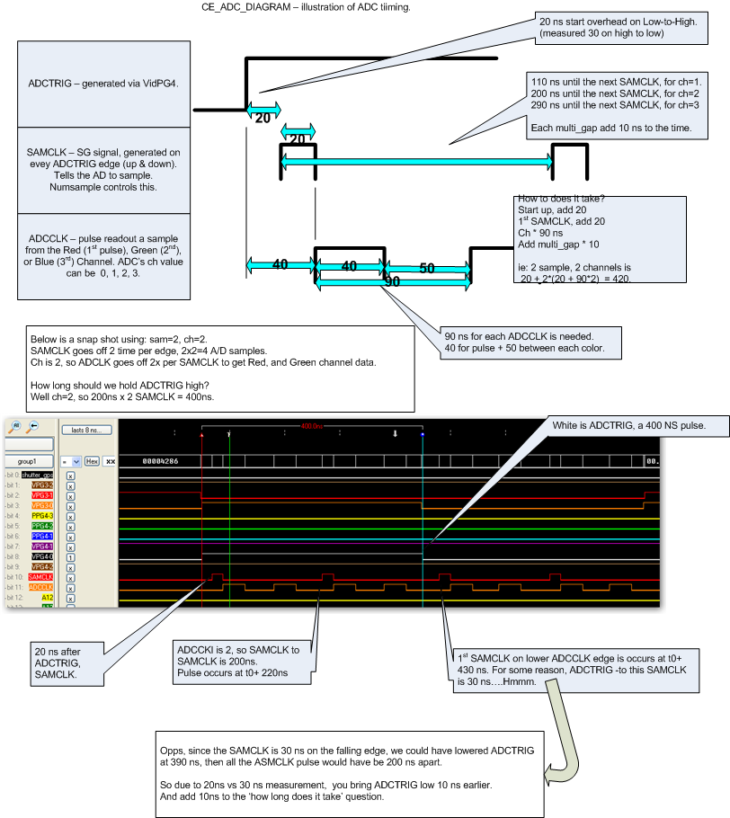
Clocking Engine ADC option
Rising and falling edge can trigger an A/D conversion. The parameter ADC_Sample
controls this, where:
ADC_Samples = 0 means 0 converts.
1 means 2 converts (SAMPCLK goes on rising AND falling edge of ADCTRIG).
2 means 4 converts, etc.(2 SAMPCLK on rising edge, 2 on falling).
SAMCLK = when ad are sampled(?).
ADCCLK = when value are readout.
The CE command is: ce_put(ce, CE_PARAM_ADC| adc);
where adc = (numsample << 10) | /* ssss ss-- ---- ---- */
(numchannels << 8 ) | /* ---- --cc ---- ---- */
(multisample_gap ) /* ---- ---- mmmmm mmmm */
numsample = number of SAMPCLK (or AD samples) per edge of ADCTRIG.
numsample is 0 to 63.. but number of AD samples per pixel is 2*numsample.
numchannels = each AD has a red, greenm and blue channel. This tells hardware what
value are: 1=R, 2=RG, 3=RGB. (use zero if numsample is 0).
multisample_gap = adds time between SAMPLECLK pulses. Range is 0 to 255 (0xff)
Each value adds 10 ns of time. 0 to 2550 ns.
ce_put(ce, CE_PARAM_ADC| adc) take 30 ns.
How does ADC option affect how you should used PG3?
Well, don't start another ADCTRIG until the current one is finish..The operation will take:
nsec = 20 + 20; /* 20 startup, 20 for 1st SAMCLK */
nsec = sam * (90 * ch); /* 90 per chan x numsamples */
nsec = 2*nsec + 10; /* x2 for 2 ADCTRIG high-to-low, and 10ns since 1st SAMCLK is 30ns. */
 Unipolar Digitial Write Register(?), aka bitbanger-
19 output line for general purpose output.
How to change hardware values:
unsigned int reg;
ce_put(ce, CE_PARAM_UPDWR_LO | (reg&0xFFFF));
ce_put(ce, CE_PARAM_UPDWR_HI | (reg>>16));
ce_put(ce, CE_CMD_UPDWR);
Q: Where are the bits defined.
Q: Timing: Tony measured on 3/19/2010
CE_CMD_UPDWR takes 50 ns.
CE_PARAM_UPDWR_LO takes 30 ns.
CE_PARAM_UPDWR_HI takes 30 ns.
Waits in the Clocking Engine
How does one do waits?
CE_CMD_DELAY | CE_ITER(i)
Q: Timing: Each ITER is 100 usec, or 100,000 ns.
CE_CMD_NOP | CE_ITER(i)
Q: Timing: CMD_NOP is 10ns + 10 per iter?
Q: Tony's timing test with stargraps and al_ck_ce_cmd_delay().
CMD_DELAY with 9999 ITER takes: 1000106 usec
CMD_DELAY with 19999 ITER takes: 2000206 usec (what is wrong).
t2 1000 = 0.001 s - CMD_DELAY | 9 = 0.001001
t2 5000 = 0.005 s - CMD_DELAY | 49 = 0.005001
t2 100000 = 0.1 s - CMD_DELAY | 999 = 0.100011
t2 500000 = 0.5 s - CMD_DELAY | 4999 = 0.500051
t2 1000000 = 1 s - CMD_DELAY | 9999 = 1.000101
t2 5000000 = 5 s - CMD_DELAY | 19999,19999,9999 = 5.000501
t2 10000000 = 10 s - CMD_DELAY | 19999 x 4 = 10.001001
CMD_DELAY time is about 1.0001 times the requested time.
Shutter Close/Open
CE Functions
ce_t * ce_open( dev ) - malloc a CE data structure.
ce_close( ce ) - frees the CE data structure.
ce_put( ce, CMD ) - puts data in the CD FIFO.
ce_fifostatus_free( ce ) - returns number of free FIFO entries.
ce_fifostatus_used( ce ) - return number of used FIFO entries.
ce_flush(ce) - blocks until the FIFO is empty.
ce_go( ce, x)
Reading clock on PPC Computer
tk_beg = get_ticks(); /* get CPU tick on a 300Mhz computer; equals 300000000 on SGIR */
usec = ticks2usec(tk_end-tk_beg); /* to usec */
msec = (tk_end-tk_beg)/(get_tbclk()/1000); /* to msec */
float way.. PPC is 300MHz.
nsec = tick / 0.3
usec = tick / 300
msec = tick / 300000
Other?
Q: printf on 'long long'? tried %lld %qd ... don't work!
testing
Unipolar Digitial Write Register(?), aka bitbanger-
19 output line for general purpose output.
How to change hardware values:
unsigned int reg;
ce_put(ce, CE_PARAM_UPDWR_LO | (reg&0xFFFF));
ce_put(ce, CE_PARAM_UPDWR_HI | (reg>>16));
ce_put(ce, CE_CMD_UPDWR);
Q: Where are the bits defined.
Q: Timing: Tony measured on 3/19/2010
CE_CMD_UPDWR takes 50 ns.
CE_PARAM_UPDWR_LO takes 30 ns.
CE_PARAM_UPDWR_HI takes 30 ns.
Waits in the Clocking Engine
How does one do waits?
CE_CMD_DELAY | CE_ITER(i)
Q: Timing: Each ITER is 100 usec, or 100,000 ns.
CE_CMD_NOP | CE_ITER(i)
Q: Timing: CMD_NOP is 10ns + 10 per iter?
Q: Tony's timing test with stargraps and al_ck_ce_cmd_delay().
CMD_DELAY with 9999 ITER takes: 1000106 usec
CMD_DELAY with 19999 ITER takes: 2000206 usec (what is wrong).
t2 1000 = 0.001 s - CMD_DELAY | 9 = 0.001001
t2 5000 = 0.005 s - CMD_DELAY | 49 = 0.005001
t2 100000 = 0.1 s - CMD_DELAY | 999 = 0.100011
t2 500000 = 0.5 s - CMD_DELAY | 4999 = 0.500051
t2 1000000 = 1 s - CMD_DELAY | 9999 = 1.000101
t2 5000000 = 5 s - CMD_DELAY | 19999,19999,9999 = 5.000501
t2 10000000 = 10 s - CMD_DELAY | 19999 x 4 = 10.001001
CMD_DELAY time is about 1.0001 times the requested time.
Shutter Close/Open
CE Functions
ce_t * ce_open( dev ) - malloc a CE data structure.
ce_close( ce ) - frees the CE data structure.
ce_put( ce, CMD ) - puts data in the CD FIFO.
ce_fifostatus_free( ce ) - returns number of free FIFO entries.
ce_fifostatus_used( ce ) - return number of used FIFO entries.
ce_flush(ce) - blocks until the FIFO is empty.
ce_go( ce, x)
Reading clock on PPC Computer
tk_beg = get_ticks(); /* get CPU tick on a 300Mhz computer; equals 300000000 on SGIR */
usec = ticks2usec(tk_end-tk_beg); /* to usec */
msec = (tk_end-tk_beg)/(get_tbclk()/1000); /* to msec */
float way.. PPC is 300MHz.
nsec = tick / 0.3
usec = tick / 300
msec = tick / 300000
Other?
Q: printf on 'long long'? tried %lld %qd ... don't work!
testing