Incremental Encoder Problems
This is an illustrated explanation of the declination incremental encoder fault that had been causing the poor pointing over the last few years. Actually we didn't know it but we had two problems; the declination fault discussed here, and an unreliable hour angle encoder. The latter problem was discovered when we switched hour angle and declination encoder assemblies; the declination encoder unit itself was OK, its mount was being pressed against by the motor housing (illustrated below).
When the declination assembly was placed in the hour angle position, the HA pointing accuracy improved from around 3 arcsec RMS fit of the error surface to less than 1 arcsec fit. After correcting the declination situation, the former HA incremental encoder now in the dec position produced 3 arcsec RMS fit, as it did in the HA position. We have since found that it is producing spurious south displacment counts when going north. A new encoder is on order. When it is installed, we expect both axes to fit the pointing error surface to about 1 arcsec each.
Following are a series of photographs illustrating the way the incremental encoders work, and what was wrong at the declination encoder mount. The arrangement of the encoder is the same for both axes. Three of the photographs are at the hour angle axis because the cramped declination installation gives little room for taking photographs. Thanks to Lars for getting me checked out with the digital camera.
It's best to have a separate window for the full size photographs, so you can look at the picture details at the same time as the text in this document. The photographs may come up in a separate window. If not, try clicking on the thumbnail view with the right mouse button. In Windows Netscape, "Open in New Window" is the first item in the right click menu. Otherwise, check your browser options for selecting a new window for graphic links.
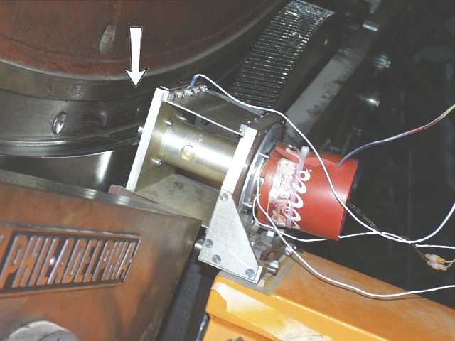
1. Overview of the encoder mount:
(Click on picture for full size version)
This is the hour angle encoder assembly from the west side. The arrow points to the encoder roller, which rolls against the milled surface near the edge of the main gear. You can see one of the two motor driven pinion gears beyond it, which drive the main gear. No, we don't get our incremental encoders from Coca Cola. What you see is an insulated foam soft drink holder, converted to a heater blanket. (These encoders can't operate under 60º F.) The actual encoder is under the heater blanket.
The cylinder between the encoder and the roller contains a coupling shaft with ball bearings. Notice the thin aluminum circular plate between the heater blanket and the thick square aluminum plate. The incremental encoder is actually mounted to the thin plate, which is the rotational reference for the encoder. It extends down as a long arm fixed at the bottom against a pin. The rest of the encoder assembly, including the thick square plates, supports the encoder roller shaft and provides spring tension for the roller against the main gear surface.
2. The mount from the other side:

This view shows the indentation in the encoder mount we had milled into the metal. You can see that the corner of the drive motor housing is within an inch or so of that milled area. In the declination position, the corner of the motor housing actually pressed against that part of the encoder assembly, distorting it and producing variable performance depending on the state of the flexure, which changes with hour angle position.
3. Encoder Mount Arm
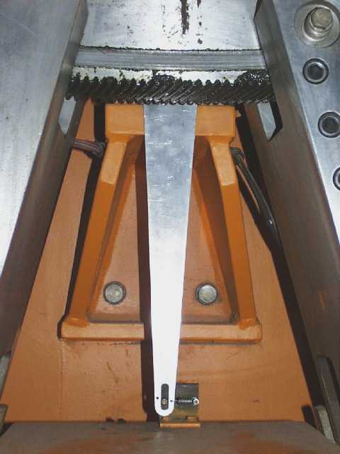
The long, vertical arm is the lower part of the thin circular aluminum plate to which the incremental encoder is mounted. (The encoder assembly is not visible behind the gear.) This arm is the rotational reference for the encoder, and is kept from freely rotating by a spring at the lower end which pulls it against a pin within the slot. The slot gives the encoder a radial degree of freedom which allows for eccentric runout of the roller surface on the main gear. When Doug N. and I inspected the encoder assemblies, this spring was defective and the declination spring was missing.
You can see in this view a short section of the main gear, with grease-darkened beveled teeth.
4. Declination encoder
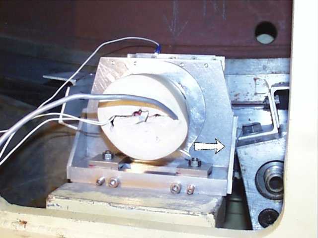
Now we are finally at the declination encoder. This is an end view, the only view accessible here, showing the foam heater blanket (not Coca Cola this time) at the back of the encoder. The arrow points to where the corner of the motor mount almost impinges against the side of the encoder assembly. Before we milled out the recess in both encoder assemblies, it did press hard against it, distorting and misaligning the assembly. Doug Neill noticed this and flagged the situation.
5. Close-up of area of former conflict:
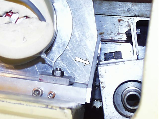
The encoder assembly and motor mount assembly are illustrated here in close-up. It was not possible to photograph the milled out area in that restricted space, but you can see that there is now a millimeter or two of clearance. Or, take my word for it. When you actually inspect it, you can see air between the structures. We need to check this from time to time. It may be that the telescope mount is sagging over time and the problem may occur again. We didn't want to mill out more metal than absolutely necessary so we wouldn't weaken the encoder mount.
These pictures of the declination encoder have been rotated a quarter turn from their actual orientation for clarity in comparing them to the HA encoder pictures.
Jim Harwood