NASA InfraRed Telescope Facility(IRTF), Institute for Astronomy, University of Hawaii
|
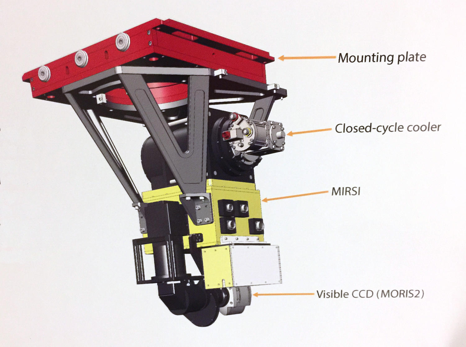
MIRSI: 2-20 micron spectrograph and imager NASA InfraRed Telescope Facility(IRTF), Institute for Astronomy, University of Hawaii |


| Contact Mike Connelley for further information or assistance |